Air Squared Articles
Eliminating Fuel Cell Parasitic Loading Using Scroll Expansion
A Hybrid Hydrogen Pump can potentially offer a substantial push for fuel cell advancement.
Written By Bryce Shaffer, PhD, Technology Director at Air Squared, LLC
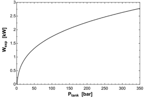
Because of their higher power density, energy storage through fuel cells can offer a unique advantage over batteries in portable applications. The power density of a fuel cell can be increased through high-pressure storage of hydrogen (on the order of 350 barg). Current systems will throttle the high-pressure supply gas down to the system pressure before circulation. By expanding the supply gas, through use of a positive displacement expansion machine, the potential energy of the compressed hydrogen can be recovered. Assuming polytropic expansion and constant supply gas temperature, Figure 1 shows the theoretical power output with tank pressure. The proposed system uses scroll expansion technology to extract the potential energy of the hydrogen storage shown in Figure 1.
The expander is implemented through the use of a hybrid hydrogen pump (HHP), a patented concept developed by Air Squared. The HHP includes both an expander for expanding the storage gas down to system pressures and a compressor for recirculating hydrogen through the fuel cell stack. By coupling the expander with the current reactant management equipment, the total parasitic loading from these components can be reduced or possibly eliminated.
The HHP Concept
In a scroll machine, compression and expansion is achieved by relative contact between two spiral curves. As one curve moves relative to the other, multiple crescent-shaped pockets are formed that decrease in size as one curve translates along a closed continuous path. When Leon Crux originally invented the scroll machine in 1905, his original intent was for it to be used as an expander in steam power applications. Unfortunately, the existing manufacturing capabilities could not cater to the high tolerances required to achieve compression. Today, the scroll is being widely adopted in the refrigeration industry and continues to replace traditional positive displacement compressors. In the fuel cell industry, the scroll compressor is being widely adopted as a standard for oxygen circulation, due to its easy oil-free implementation, low vibration, minimal noise, and high efficiency.
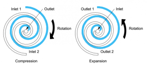
Operation of the compressor is dependent on the scroll involute wrap direction, as well as the rotational direction. For a scroll compressor, a suction port is located at the end of each involute spiral, as depicted in Figure 2 (a). As the compressor orbits, two compression chambers progress from the outside-in before eventually merging in the center and discharging through the outlet nozzle. By changing the wrap direction or the rotational direction, the scroll can operate in expansion mode. The suction and discharge nozzle switch places from their compressor mode placement as depicted in Figure 2 (b).
The HHP includes both an expander and compressor by changing the wrap direction at some spiral midpoint. By doing this both the compressor and expander can be included in the same scroll pack. The expander is located in the center, while the compressor is located on the outside. Figure 3 shows this basic concept.
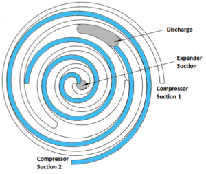
For safety reasons, the gas is first throttled down to an intermediate working pressure of 30 barg. As can be observed from Figure 1, 30 barg will provide roughly 1 kW of power for ideal polytropic expansion. From here, the gas enters the suction port of the expander located at the center of the HHP, as shown in Figure 3.
Fuel cells maintain higher efficiencies when operating fuel-rich on the hydrogen side. The excess hydrogen, coming out of the fuel cell stack, is recirculated in order to maintain consistent 50% excess hydrogen. In order to overcome pressure drops throughout the system, the compressor side of the HHP is used. The recirculated gas comes in through the outer suction port shown in Figure 4. After compression, both the compressed recirculated gas and the expanded supply gas merge at the spiral midpoint and discharge through a common outlet port.
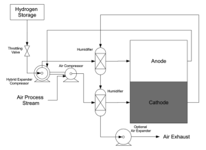
In current systems, the two largest contributors to reactant management power consumption are the hydrogen recirculation pump and the air compressor. By installing the HHP on the same shaft as the air compressor, as shown by the linkage between the compressor and expander in Figure 4, these loads can be reduced or possibly eliminated. Another option of consideration is the exhaust gas on the cathode side of the fuel cell. This gas is normally used to heat the inlet gas and re-vaporize any moisture in the two process-streams. After passing through the heat exchangers, the gas can be sent through an expander to recover some energy from the hot-air exhaust. This could also be incorporated into the air compressor.
Conclusion
Reactant management represents the largest cost driver in balance of plant for fuel cell systems. These systems can share anywhere from 19% to 41% of all fuel cell cost. A large portion of this cost can be attributed to the energy required for reactant management. With energy prices rising and demand for more efficient alternatives to current power systems, the Hybrid Hydrogen Pump can potentially offer a substantial push for fuel cell advancement.
